TDCR method
The TDCR method is an absolute activity measurement method specially developed for pure beta- and pure EC-emitters activity determination, in which the detection efficiency is calculated from a physical and statistical model of the photon distribution emitted by the scintillating source. As the signals delivered by the photodetectors are affected by the thermal noise of the photocathode, coincidence method must be used to remove that noise. It can be shown that there is not enough information in a 2-photodetectors system to determine the experimental detection efficiency without an additional reference source. This is why the TDCR method uses a 3-photomultipliers detector, allowing the observation of 3 kind of double coincidences (2-photodetectors) and triple coincidence (3-photodetectors).
This absolute measurement method relies on 3 fundamental assumptions concerning the statistics of the emitted light, the detection threshold of the counter and the description of the scintillator non-linearity.
Hypothesis #1: for a monoenergetic electron interacting with the scintillator, the number of photons are emitted according to a Poisson law.
If the energy of the electron E, released in the scintillator produces a mean number m of photons, the statistics of the number of photons emitted by the vial follows a Poisson law: the probability of emission of x photons for a mean value m is :
\(P(x|m) = \displaystyle{\frac{m^x e^{-m}}{x!}}\)
Hypothesis #2: the detection probability of one photon is not zero.
Detection efficiency is the detection probability which is the complement of the non-detection probability. This second hypothesis allows one to consider that the non-detection probability is the probability to observe 0 photon for a mean value of m. Introducing this in the Poisson formula, we get:
Detection efficiency = \(1-P(0|m) = 1-e^{-m}\)
This statistics is also true for the observable, which is the photoelectrons distribution. This is a result of a cascade of three random processes: Poisson distribution for the light emission, multinomial distribution for the behaviour of photons inside the optical chamber and binomial distribution for the photoelectric process in the photocathodes. It can be shown that these processes can be resumed in a whole Poisson process.
For a 3-PMT counter (1/3 symmetry) with a quantum efficiency ν, we get:
- Detection efficiency for 1-PMT: \(R_1 = 1-e^{-\frac{\nu m}{3}}\)
- Detection efficiency for 2-PMT in coincidence: \(R_2 = (1-e^{-\frac{\nu m}{3}})^2\)
- Detection efficiency for 3-PMT in coincidence: \(R_T = (1-e^{-\frac{\nu m}{3}})^3\)
- Detection efficiency for the logical sum of double coincidence events: \(R_D = 3(1-e^{-\frac{\nu m}{3}})^2-2(1-e^{-\frac{\nu m}{3}})^3\)
Hypothesis #3: the number of photons emitted is a non-linear function of energy.
The LS light emission process is not linear, the mean number of photons emitted being non-proportional to the energy released in the scintillator by the ionising radiation. The light emission yield relies on the linear energy transfer. One can find in the literature many models describing this behaviour. The simpler is a semi-empirical relation, described by Birks, and giving the mean number of photons emitted as a function of the energy released in the scintillator, E, and the linear energy transfer dE/dx:
\(m(E)=\displaystyle{\int_0^E}\displaystyle{\frac{AdE}{1+kB\frac{dE}{dx}}}\)
where m(E) is the mean number of photons produced by the energy E, A is a free parameter characterising the LS-cocktail efficiency, kB is a semi-empirical parameter and dE/dx is the linear energy transfer calculated using the Bethe law.
Taking the three previous hypothesis into account, and assuming that the energy spectrum emitted by the radionuclide is described by a normalised density function S(E), the ratio of the probability of the triple coincidence divided by the probability of the double coincidence, TDCR, is:
\(TDCR=\displaystyle{\frac{\int_{spectrum}S(E)(1-e^{-\eta})^3}{\int_{spectrum}S(E)(3(1-e^{-\eta})^2-2(1-e^{-\eta})^3)}}\) with \(\eta=\displaystyle{\frac{\nu}{3}}\displaystyle{\int_0^E}\displaystyle{\frac{AdE}{1+kB\frac{dE}{dx}}}\)
The frequencies of triple and double coincidences are recorded by the LS-counter. For a large number of events, the frequency ratio converges toward the probability ratio. The detection efficiency calculation algorithm is thus, to find out the figure of merit h, for which we have:
\(TDCR=\displaystyle{\frac{T_{experimental}}{D_{experimental}}}\)
– For pure beta radionuclides, there is an unique solution and the detection efficiency is a monotonous function of the experimental TDCR.
– For certain kind of radionuclides, including the one decaying by electron capture, one TDCR value can correspond to up to three detection efficiency values. In that case the ambiguity can be solved by using several counting conditions for a single sample, for example by defocusing the PMT’s or by adding coaxial grey filters around the vial.
BIBLIOGRAPHY
- M.N. Péron, P. Cassette (1996), Study of liquid scintillator response to low-energy electrons with a Compton coincidence experiment, Nucl. Instr. Meth. Phys. Res., A369, pp.344-347
- B.R.S. Simpson, B.R. Meyer (1992), Direct determinationof the activity of non-gamma-emitting radionuclides by the TDCR efficiency calculation technique: a review of the present status, NAC Report, NAC/92-02, September 1992
- R. Vatin, Mesure absolue de l’activité des radionucléides émetteurs bêta purs par scintillation liquide à l’aide d’un détecteur à trois photomultiplicateurs. Bulletin du BNM, n°85, juillet 1991
- Grau Malonda A., Coursey B.M., Calculation of beta-particle counting efficiency for liquid scintillation systems with three phototubes. Appl. Radiat. Isot., 39, 1191-1196, (1988)
- Cassette P. and Vatin R., Experimental evaluation of TDCR models for the 3-PMT liquid scintillation counter. Nucl. Instr. Meth. Phys.Res., A312, 95. 1992
- Broda R. and Pochwalski K., The enhanced triple to double coincidence ratio (ETDCR) method for standardization of radionuclides by liquid scintillation counting. Nucl. Instr. Meth. Phys. Res., A312, 85.1992.,pp. 85-89
- Péron M.N. and Cassette P., Study of liquid scintillator response to low-energy electrons with a Compton coincidence experiment. Nucl. Instr. Meth. Phys.Res., A369, 344. 1996
- A. Grau Malonda and E. Garcia-Toraño, Evaluation of counting efficiency in liquids cintillation counting of pure b-ray emitters. Int. J. Appl. Radiat. Isot.Vol 33, 249-253, (1982)
- A. Grau Carles, A. Grau Malonda (1989), Electron-capture standardization with a triple phototube system, Anales de Fisica, Ser.B, Vol.85
- K. Pochwalski R. Broda and T. Radoszewski , Standardization of pure beta emitters by liquid scintillation counting, Appl. Radiat. Isot.39 (1988)
- R. Broda, K. Pochwalski, T. Radoszewski (1988), Calculation of liquid – scintillation detector efficiency, Appl. Radiat. Isot., vol.39, No. 2, pp.159-164
- BIPM Monographie (1986), No.3, BIPM, Sèvres, France
- J.B. Birks, Proc. Phys. Soc., A64, (1951)
- A. Grau Malonda (1982), Counting efficiency for electron-capturing nuclides in liquid scintillator solutions, Int. Appl. Radiat. Isot., Vol.33, pp.371-375
- K. Pochwalski, T. Radoszewski (1979), Disintegration rate determination by liquid scintillation counting using the triple to double coincidence ratio (TDCR) method, IBJ Report, INR 1848/OPiDI/E/A
- D.L. Horrocks (1974), Application of liquid scintillation counting, Academic Press, 80,SXIII, London
- J.B. Birks (1964), The theory and practice of scintillation counting. Pergamon Press, Oxford
THE 3-PHOTODETECTORS LIQUID SCINTILLATION COUNTER
3-Photodetectors LS-counters can be realised in different ways but one must follow some design rules specific to the method.
As an example, the LNHB counter is described here.
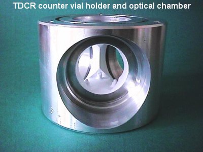
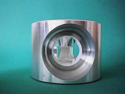
The liquid scintillation counter is composed of two parts: an optical chamber with photomultiplier tubes and a signal processing unit.
The optical chamber is designed for the use of standard 20 ml vials.
Three very high gain photomultiplier tubes, facing the vial, are disposed 120° apart.
The inner walls of the optical chamber are coated with a diffusive reflector paint.
The PMT used must be able to detect mono-photoelectron events. In the LS-counters developed at LNHB (France) and RC (Poland), BURLE-RCA 8850 PMT are used and the electrical potentials of PMT’s electrodes are raised up to 800 V for the first dynode and 2800 V for the anode, in order to obtain a good resolution and sensitivity to mono-photoelectrons events. The potential of the focusing electrode can be adjusted in order to change the detection efficiency. This can also be done by using coaxial grey filters around the vials.
PMT’s outputs are connected to fast amplifiers and coincidence information are elaborated by the use of logical units via amplitude discriminators and dead-time controlled gates. In order to avoid the influence of any kind of afterpulses, an extending-type dead-time signal is imposed to the system, closing the channel gates for at least 40 µs, this 20 ns after the detection of a pulse in either one of the 3 channels. All these functions are processed by the module MAC3. Eventually, all the coincidence and time signals are sent to a microcomputer via a CAMAC bus and an IEEE 488 interface.
All the setting operations and data acquisitions are under the control of a FORTRAN software, specific of the IEEE 488 and the CAMAC interface.
The TDCR LS-counter is also connected to an amplitude analyser for the control of the LS spectrum. The electrical pulses, issued from an intermediate dynode of each PMT are sampled and integrated during a 20 ns time window and held for further amplitude analysis by a commercial ADC. The sampling gate is triggered by the detection signal of the counting unit and is inhibited by the deadtime signal. The recorded spectrum is then representative, in terms of sampling, of the pulses taken into account in the counting system. The sampling gate can also be validated by the coincidence information delivered by the counting system, thus allowing the examination of both coincident and non-coincident spectra.
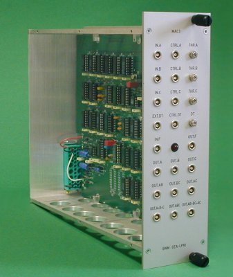
MAC3 is an electronic module specialised in the processing of pulses delivered by three-photomultipliers liquid scintillation counting system.
TDCR module MAC3
Front panel inputs/outputs
Inputs
IN.A, IN.B, IN.C: PMT’s pulse signals. Fast NIM inputs, 50 Ω impedance. The input level must be in the -100 mV to -5 V range. This input could be directly connected to the anode output of the PMT’s but a fast amplifier (for example LeCroy Model 612AM) might be necessary to raise the signal over the noise level.
IN.F: clock signal. NIM or TTL input, depending on the position of the switch ST1 (on the printed circuit board). ST1 closed: NIM level, 50 Ω impedance. ST1 opened: TTL level, 1 kΩ impedance. The frequency and cyclic ratio of this signal is not imposed, as the module provides an internal shaping of this pulse. At LNHB, we generally use a 10 kHz signal with a 1:1 ratio.
EXT.DT: auxiliary dead-time signal input. NIM or TTL input, depending on the position of the switch ST2. ST2 closed: NIM level, 50 Ω impedance. ST2 opened: TTL level, 1 kΩ impedance.
Warning: inputs IN.F and EXT.DT are equipped with an automatic polarity detection circuit; input signal must be either positive or negative but not both.
The closed position of ST1 and ST2 is reached when the cursor of these switches is toward the front face of the module.
Outputs
CTRL.A, CTRL.B, CTRL.C: analog level for the input discriminator threshold.
Warning: the outputs are not bufferised, so a high impedance voltmeter must be used for the level adjustment and these outputs must be deconnected during normal module operation. For a safe discriminator operation (i.e. far over the noise level), the threshold level must be greater than 100 mV.
OUT.A, OUT.B, OUT.C: PMT’s pulse outputs sampled by the dead-time signal. NIM level, 50 Ω impedance and 500 ns duration.
OUT.AB, OUT.BC, OUT.AC: double coincidence outputs, sampled by the dead-time signal. NIM level, 50 Ω impedance and 500 ns duration.
OUT.ABC, OUT.AB+BC+AC, OUT.A+B+C: respectively triple coincidence, logical sum of double coincidences and logical sum of PMT’s outputs sampled by the dead-time signal. NIM level, 50 Ω impedance and 500 ns duration.
OUT.F: clock output signal sampled by the dead-time signal. NIM level, 50 Ω impedance, frequency and cyclic ratio similar to the one of the clock signal injected in IN.F. The number of pulses counted at OUT.F gives the live-time of the counter.
CTRL.DT: dead-time signal, NIM 50 Ω output. The dead-time base duration can be adjusted between 10 µs and 100 µs with POT 4.
BIBLIOGRAPHY
J. Bouchard and P. Cassette, MAC3, a coincidence unit for the TDCR method. To be published in ARI.


